
beacon antenna
As I had explained a while ago, this beacon must have a good antenna.
Finally having finish the electronic board, I was able to take care of it, just to confront theory with reality.
The theory says that the Sigfox network operates on 868MHz. That 868MHz is a wavelength of 34,6 cm. And so we can make an antenna of 17,3 cm for a half-wave, or 8,6 cm for a quarter-wave.
But problem: The anemo is not big enough to put an 8 cm straight rod inside. We must therefore find a way to bend the antenna in a smart way so that it fits into the box while maintaining correct performance.
 |
| An antenna that did not fit in the box. Shortly before Di Caprio drowned. |
Except that making a crooked antenna that works isn't that easy. Even at Apple, they planted when they made the iPhone 4.
Everyone has their own way
« There are two ways to learn antenna design. One way is to go to grad school. I’ll teach you the other way. »
On his blog, Colin Karpfinger explains that there are two ways to learn how to design an antenna. The first is to go to school. The second, …
Here, no numerical simulations or scholarly calculations. We test, and we advise.
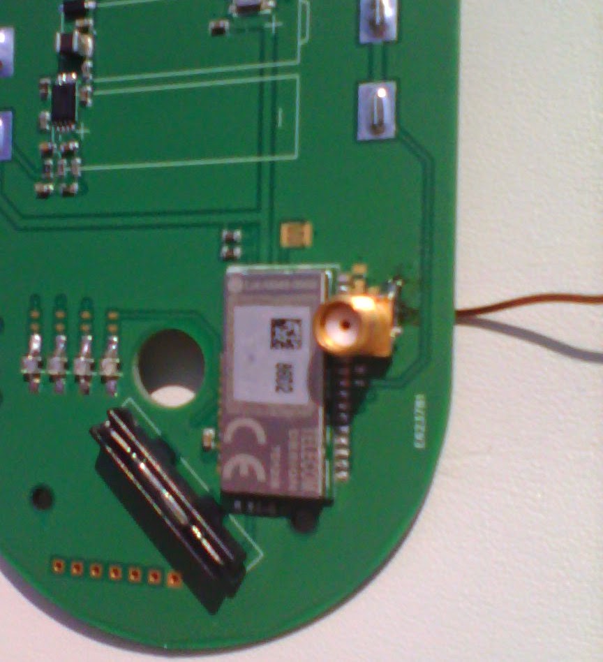
I start by soldering a copper wire on the board, as a “raw material” for our antenna. I also solder a small connector at the point of origin of the signal, the time of the measurements.
On this small connector, comes to connect a large coaxial cable.
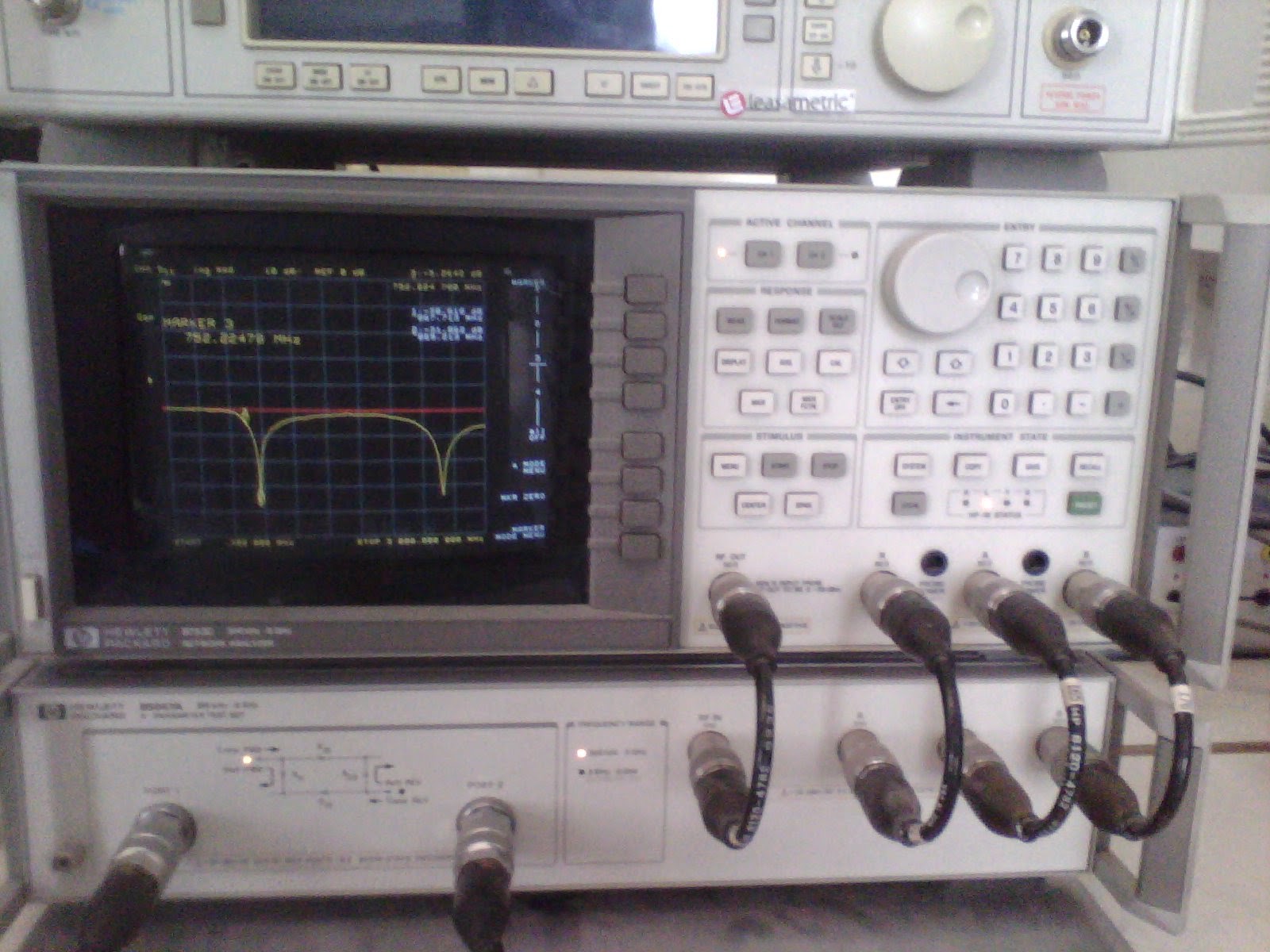
And at the end of this thick cable, the instrument of the demon!
In high school, the oscilloscope gave you pimples? Here is the VNA, the Vector Network Analyzer or vector network analyzer among us French speakers.
This little magic device can do a lot of things. In particular, it gives us the power transmitted by the antenna as a function of the frequency.
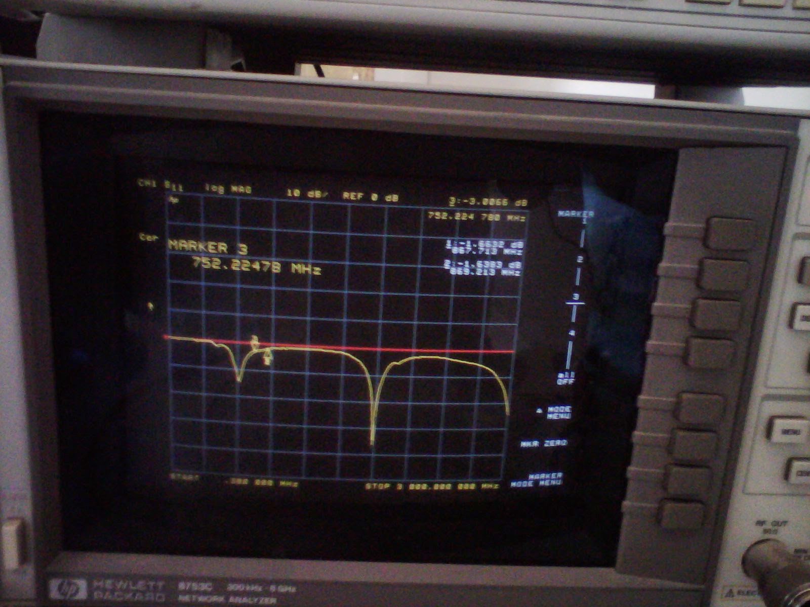 |
| Here, an antenna that does not work well for 868 MHz |
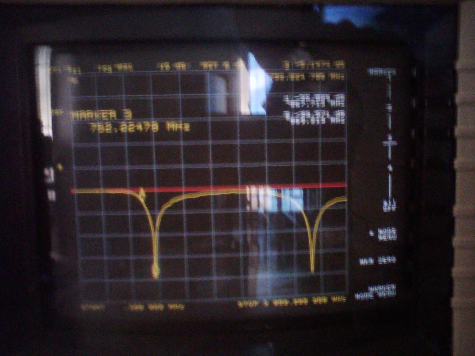 |
| A few nudges later, the antenna just got to the right frequency. |
Bonus: Did you like the emagram? You'll love theSmith's Slaughter ! Nicely defined by wikipedia as " a nomogram relating the ratio of incident and reflected guided waves along a propagation guide to the characteristic impedance variation along this guide ».
 |
| A spirograph at €30! |
Concretely, this thing makes it possible to measure the impedance of the antenna. Basically, if the antenna does not have sufficient impedance, it sends too much power back to the transmitter and it can burn it out. Here it's won, we have 50 ohms. If that had not been the case, it would have been necessary to make a impedance matching by adding some components to the circuit.
Do not bend
With a straight wire, I managed to have a very good antenna. Up to -34dB! But the straight wire does not fit in the box. So you have to twist it.
And there is the drama: from the slightest fold, the performance of the antenna deteriorates enormously. I tried lots of different shapes. Not even a way to reach -10dB. We level off at -5dB. And again, here we are only talking about gain, I have not even mentioned the issues of signal polarization.
After a whole day of fruitless tests, I had to resign myself: we will not have an antenna satisfying the 3 criteria: size, frequency and gain. Or in any case, it requires means that I don't have.
Basic but effective
I am very disappointed. I really thought I could completely integrate the antenna into the anemo.
But in the end, what is most important? Have a design beacon or have a beacon that picks up well even in remote areas?
I am therefore moving towards a “classic” antenna, outside.
But even the classic antenna, you have to think carefully about how to place it.
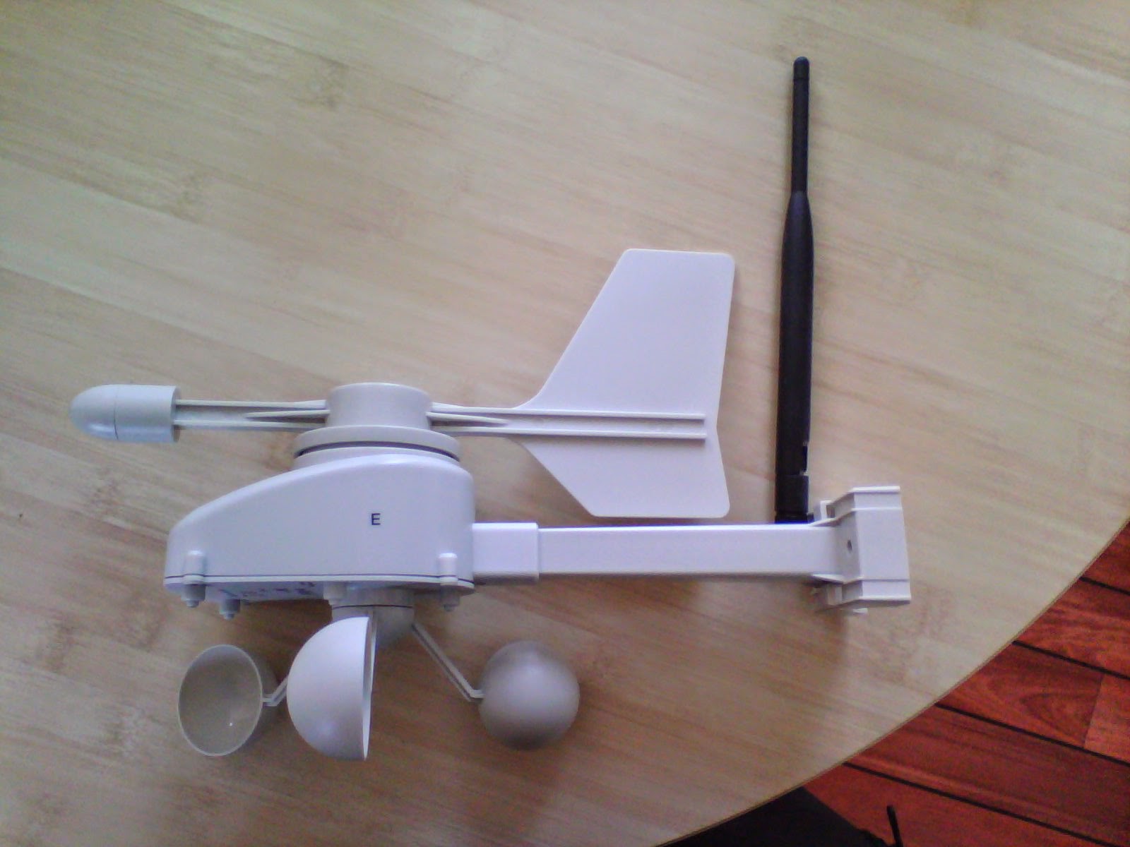
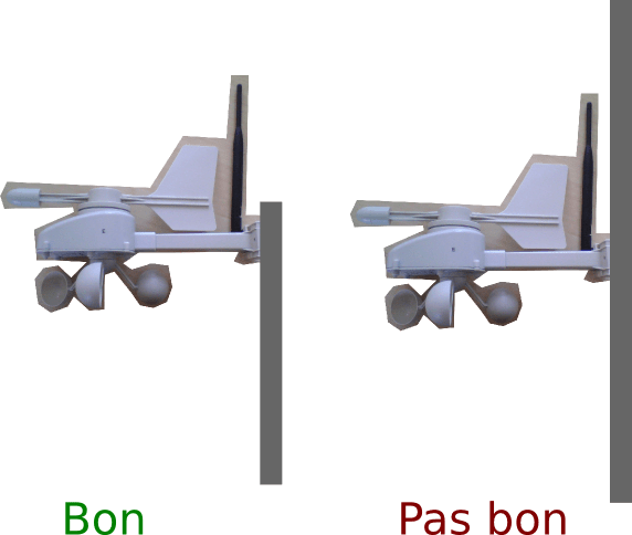
The most obvious is vertically, upwards. But the weather vane gets in the way. It must therefore be placed at the end of the “arm”. The concern is that suddenly it will end up near the post, which risks disturbing the signal.
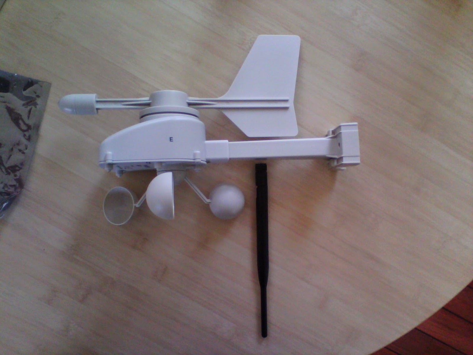
The second solution is upside down. As the cups are shorter than the weather vane, it can be moved a little further from the post.
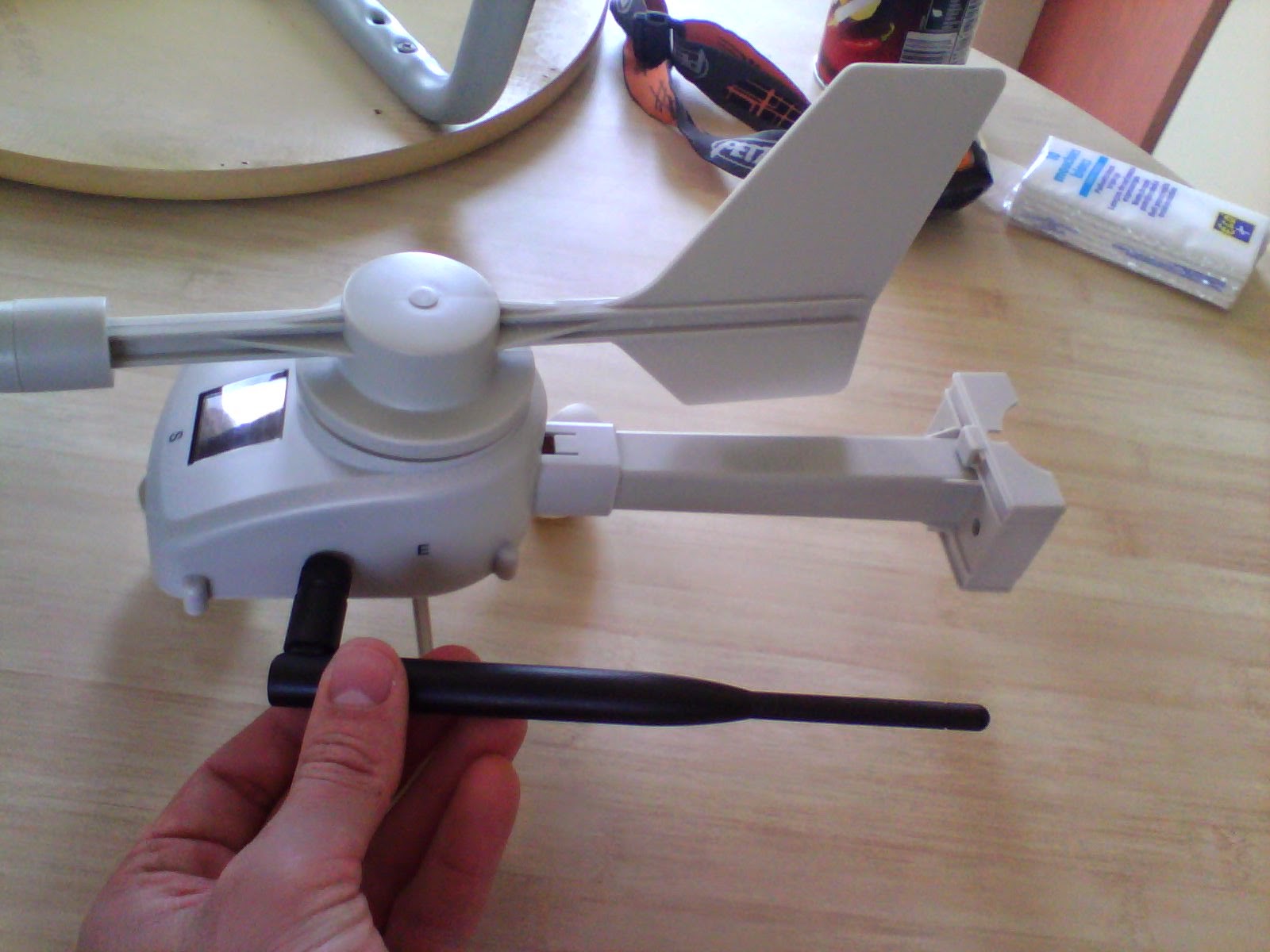
The third solution is on the side, horizontally.
The thing is that horizontally, the antenna only emits perpendicular to it. So there is a dead zone. It will therefore be necessary to orient it well once there. It seems complicated to me.
So I think the first solution seems the most appropriate. As in general the beacon is placed at the top of the post, it should not interfere.
If anyone has a better idea, don't hesitate 🙂
This article tells you about the birth of Piou Piou, the first 100% autonomous and affordable sensor to measure the wind live, even where there is no electricity or internet.
Discover Pioupiou on his website: http://pioupiou.fr



8 thoughts on “ beacon antenna »
This comment has been removed by the author.
Do you see a possibility of deporting the antenna, which would make it possible to adapt on a case-by-case basis?
Hello there are also two solutions: horizontally (as on the third solution) but forwards. there might be less dead zone (??)
Or in the same spirit forward horizontally as a nose or beak 😉
sportily
Matthieu rightly, you would have to deport the antenna by running the cable along the pioupiou barrel
there is that too
http://www.sectron.eu/products/249-antenna-internal/252-gsm-pcb/1120-antenna-gsm-umts-uma-series-quad-band-mmcx-90%C2%B0.html
olive brunetto
Ah the TP with the VSA! And at Sigfox, would there be someone to help you? I worked a long time ago with someone who is there now: a real antenna wizard!
Yes, but it's called a support service and the price is not negligible. This is what I will do for the “industrial” version of the product. At the moment I don't have the budget for...
And unfortunately the Sigfox teams are already very busy, so it's not possible to have free support.
And why not sideways down? And if not, the 8.6cm do not fit the entire length of the thing, including the clip?
Have you tried 1/8 wave if not? Is it too low?